
Integrated modern
plastic products factory
plastic products factory
The information comes from: Internet Published on: 2022-11-07
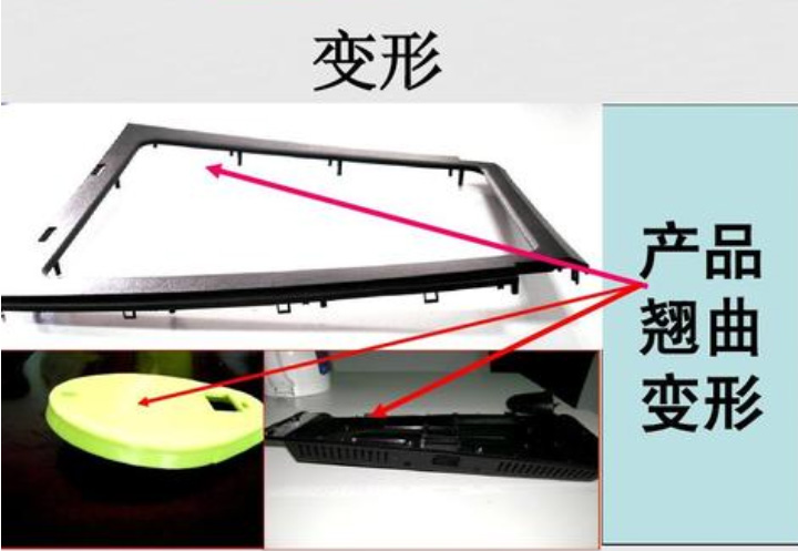
Warping deformation refers to the distortion and unevenness of the shape of injection molded products, deviating from the shape accuracy requirements of the parts. It is one of the common and difficult to solve product defects in injection mold design and injection production.
With the development of the plastic industry, especially the electronic information industry, there is an increasing demand for the appearance and performance of plastic products. The degree of warping and deformation of molded parts such as laptops, handheld computers, and thin mobile phones has become one of the important indicators for evaluating product quality, and is increasingly receiving attention and importance from mold designers. I hope to predict the possible causes of plastic part warping during the design phase, in order to optimize the design, reduce product warping deformation, and meet the accuracy requirements of product design.
first,Reasons for warping and deformation
Warping deformation is caused by uneven stress and shrinkage during the injection process of a product. Poor demolding, insufficient cooling, unsuitable shape and strength of the parts, poor mold design and process parameters also cause plastic parts to deform.
Uneven mold temperature and uneven internal temperature of plastic parts.
The difference in wall thickness and uneven cooling of plastic parts lead to differences in shrinkage.
The condensation pressure difference and cooling rate difference in the thickness direction of plastic parts.
When the plastic part is ejected, the temperature is too high or the force is uneven.
Improper shape of plastic parts, with bent or asymmetrical shapes.
Poor mold accuracy and unreliable positioning result in plastic parts being prone to warping and deformation.
The improper position of the feed inlet and poor injection process parameters result in obvious directional shrinkage and uneven shrinkage.
The difference in orientation between the flow direction and the molecular chains perpendicular to the flow direction results in different shrinkage rates.
Asymmetric cooling of convex and concave mold wall thickness, insufficient cooling time, and improper cooling after demolding.
second,The influence of mold structure on warpage deformation of injection molded parts
In terms of mold design, there are three main systems that affect the warpage and deformation of plastic parts, namely the pouring system, cooling system, and ejection system.
Design of sprue
The injection mold gate is a critical part of the entire pouring system, and its position, form, and number of gates directly affect the filling state of the molten material in the mold cavity, leading to plastic solidification, shrinkage, and internal stress variation. The commonly used gate types include side gate, point gate, hidden gate, straight gate, fan-shaped gate, and film gate.
The selection of gate position should minimize the flow distance of plastic. The longer the flow distance, the greater the flow difference between the internal flow layer and the external frozen layer. As a result, the internal stress caused by flow and shrinkage between the frozen layer and the central flow layer increases, and the deformation of the plastic part also increases accordingly;
On the contrary, the shorter the flow distance, the shorter the flow time from the sprue to the end of the workpiece flow. During mold filling, the thickness of the frozen layer is reduced, the internal stress is lowered, and the warpage deformation is also reduced as a result.
For precision thin-walled large plastic parts, using a center gate or a side gate will cause significant twisting deformation in the formed plastic parts due to the radial shrinkage rate being greater than the circumferential shrinkage rate; If multiple point gates or film gates are used instead, it can effectively prevent warping and deformation, so flow ratio calculation and verification must be carried out during design.
When using sprue molding, due to the anisotropy of plastic shrinkage, the position and quantity of sprues have a significant impact on the degree of deformation of the plastic part.
Distribution test of flat box shaped plastic parts with different numbers of gates: A plastic part reinforced with 15% glass fiber PA66 and weighing 1450g was used, with many reinforcing ribs along the flow direction of the surrounding walls.
Using essentially identical process parameters. Gate method: (a) Straight gate, (b) 5-4 point gates, (c) 9-8 point gates. The experimental results show that setting the gate according to b has the best effect and meets the design requirements. The gate designed according to C is worse than the straight gate, with a warpage deformation exceeding the design requirements by 3.6-5.2mm.
Multiple gates can shorten the flow ratio (L/t) of plastic, thereby making the density and shrinkage of the molten material in the mold more uniform. At the same time, plastic parts can fill the mold cavity under lower injection pressure, reducing the molecular orientation tendency of plastic, lowering internal stress, and reducing deformation of plastic parts.
Design of cooling system
During the injection process, uneven cooling rate of the plastic part will also result in uneven shrinkage of the plastic part, which leads to the generation of bending moment and causes the plastic part to warp.
If the temperature difference between the mold cavity and core of a precision flat plastic shell part is too large, the melt on the cold mold cavity surface will quickly cool down, while the material layer close to the hot mold cavity surface will continue to shrink. Uneven shrinkage will cause the plastic part to warp. Therefore, the cooling system design of injection molds should strictly control the temperature balance of the core and cavity.
For precision flat plastic shell parts, materials with high molding shrinkage and easy deformation, production tests have shown that the temperature difference should not exceed 5 °~8 °.
Secondly, the consistency of temperature on all sides of the plastic part should also be considered, that is, to maintain uniform temperature throughout the core and cavity, so that the cooling rate of the plastic part is balanced and the shrinkage is uniform, effectively preventing deformation from occurring. The design of the cooling system should be determined through rigorous process testing based on theoretical calculations. Therefore, the setting of cooling water holes on the mold is crucial.
After determining the distance from the pipe wall to the surface of the mold cavity, the distance between the cooling water holes should be minimized as much as possible. If necessary, an uneven arrangement should be used, where the cooling water holes are denser at higher material temperatures and sparser at lower material temperatures, in order to maintain a similar cooling rate. Meanwhile, as the temperature of the cooling medium increases with the length of the cooling water channel, the length of the water channel in the cooling circuit should not be too long.
Design of the ejection mechanism
The design of the ejection mechanism also directly affects the deformation of the plastic part. If the arrangement of the ejection mechanism is unbalanced, it will cause uneven ejection force and deformation of the plastic part. Therefore, when designing the ejection mechanism, efforts should be made to balance it with the demolding resistance. The cross-sectional area of the top pole should not be too small to prevent deformation of the plastic part due to excessive force per unit area.
The arrangement of the top rod should be as close as possible to the area with high demolding resistance. For precision flat plastic shell parts, as many top rods as possible should be installed to reduce deformation of the plastic parts, and a composite demolding mechanism combining top rod demolding and push plate demolding should be used.
When using soft plastic to produce large deep cavity thin-walled plastic parts, due to the high demolding resistance and the softness of the material, if the mechanical ejection method is completely used, the plastic parts will deform. If a combination of multiple components or a combination of pneumatic (hydraulic) pressure and mechanical ejection is used, the effect will be better.
third,Mold filling cooling and warping deformation
Molten plastic is filled into the mold cavity under injection pressure and cooled and solidified inside the cavity. In this process, temperature, pressure, and velocity are coupled with each other, which has a significant impact on the quality of the plastic parts.
Higher pressure and flow velocity will generate high shear stress, causing differences in molecular orientation between parallel and perpendicular to the flow direction, resulting in larger internal stresses in the plastic part. The influence of temperature on warping deformation is mainly reflected in the following aspects:
The temperature difference between the inner and outer surfaces of plastic parts can cause thermal stress and deformation;
The temperature difference between different areas of the plastic part causes uneven shrinkage;
Different temperature states can affect the shrinkage rate of plastic parts.
Therefore, strict control of appropriate injection process parameters is an important means to reduce warping deformation.
fourth,Shrinkage and warping deformation of parts
The direct cause of warpage and deformation of injection molded parts is the uneven shrinkage of the plastic parts. For the analysis of warping deformation, shrinkage itself is not important, what is important is the difference in shrinkage. In the injection molding process, the arrangement of polymer molecules along the flow direction during the injection molding stage causes the plastic to shrink more in the flow direction than in the vertical direction, resulting in warping deformation of the injection molded parts.
Generally, uniform shrinkage only causes changes in the volume of plastic parts, and only uneven shrinkage can cause warping deformation. The difference in shrinkage rate between the flow direction and the vertical direction of crystalline plastics is greater than that of amorphous plastics, and their shrinkage rate is also greater than that of amorphous plastics. Therefore, the tendency of crystalline plastic parts to warp and deform is much greater than that of amorphous plastic.
fifth,Residual thermal stress and warping deformation
During the injection molding process, residual thermal stress is an important factor causing warpage deformation. Due to the complex impact of residual thermal stress on the warpage deformation of parts, mold design is usually analyzed and predicted using injection molding CAE software.
sixth,summary
There are many factors that affect the warpage and deformation of precision flat and thin plastic parts. The structure of the mold, the thermal and physical properties of the plastic material, and the process parameters of the injection molding process all have varying degrees of influence on the warpage and deformation of the parts. Therefore, experimental research on the mechanism of component warping deformation must highlight key points and comprehensively consider various factors.